1.Fitting the Following vehicle:2008-13 Nissan Rogue Steering & Suspension Kit2014-15 Nissan Rogue Select Steering & Suspension Kit2.Package Includes:1x Part # Front Control Arm - K6214521x Part #Front Control Arm - K6214531x Part #Stabilizer Bar Link- K7500941x Part #Stabilizer Bar Link - K7500951x Part #Tie Rod End- ES8005821x Part #Tie Rod End - ES8005832x Part #Tie Rod End- some parts have grease fittings, other parts are factory sealed, but do not affect the fit and quality of the parts. Front Control Arm Ball Joint Tie Rods Sway Bar Link Steering Suspension Kit 8pcs
1.Fitting the Following vehicle:
2008-13 Nissan Rogue Steering & Suspension Kit
2014-15 Nissan Rogue Select Steering & Suspension Kit
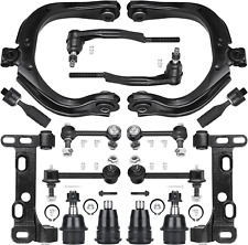
2.Package Includes:
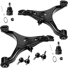
1x Part # Front Control Arm - K621452
1x Part #Front Control Arm - K621453
1x Part #Stabilizer Bar Link- K750094
1x Part #Stabilizer Bar Link - K750095
1x Part #Tie Rod End- ES800582
1x Part #Tie Rod End - ES800583
2x Part #Tie Rod End- EV800550
3.Note
Although some parts have grease fittings, other parts are factory sealed, but do not affect the fit and quality of the parts.
10 Year Warranty
Please check above compatibility list to make sure it fits your vehicle.
Suspension Control Arm Replacement Guideline:
Control arms are installed in pairs on the front and rear axle and connect the chassis to the wheels as part of the suspension. Therefore, they have a significant influence on the driving characteristics of the vehicle.
A dynamic or a comfortable driving style? The control arms are individually adjusted to the vehicle depending on the desired characteristics. They also absorb lateral movements and forces resulting from driving off and defective control arm can manifest in the following ways:
(1).Noise (squeaking, creaking, rumbling).
(2).Deteriorating driveability.
(3).Increasingly woolly and imprecise steering.
(4).Uneven tyre wear.
Tip:If the control arm is in working order, it is possible to only replace the defective bearings and joints. However, replacing bearings, control arm bushings and ball joints can be very complex and lift the vehicle using a car lift, ideally a wheel-free four-post car lift. This makes it easier to correctly tighten the control arm fixing screws.
WARNING:Depending on the axle design, the control arm may need to be secured against falling with a suitable device, e.g. a transmission lifter.
2.Treat the fixing screws and nuts of the control arm with rust solvent and leave it to work for a few minutes so that they are easier to loosen.
3.On vehicles with automatic headlight levelling, it may be necessary to detach the leveling sensor from the control arm.
Picture(C)
4.If the stabilizer is connected to the control arm, the next step is to loosen and remove the corresponding stabiliser fixing screws.
5.Loosen and remove the control arm fixing screws.
6.Loosen the ball joint at the steering knuckle with a suitable special tool (e.g. a puller).
7.Remove the old control the mounting flange of the ball joint pin on the steering knuckle with sandpaper and then with brake cleaner. Otherwise single rust particles can enter the new control arm joint via the ball pin, potentially leading to premature failure of the the new control arm with the supplied accessories and attach new fixing screws and the stabilizer and, if applicable, the leveling sensor for headlight leveling to the control arm.
NOTE:Do not tighten the fixing screws and nuts in this step, otherwise the rubber mounts will twist when the suspension compresses. This would lead to undesired preloading onf the lower the vehicle until the suspension is compressed. Depending on vehicle type, load or unload the vehicle until the required height published in the specific installation instruction is reached. This is where a wheel-free four-post car lift is advantageous, as the underside of the vehicle can still be easily accessed once lowered.
12.Tighten the fixing screws with the torque stipulated by the vehicle manufacturer.
13.Lower the vehicle all the way.
14.Measure the chassis and adjust if necessary.
15.Check and, if necessary, adjust the headlight settings on vehicles with automatic headlight leveling where the leveling sensor is attached to the control arm.
16.To conclude, test-drive the vehicle.
Ball JointReplacement Guideline:
If there is a knocking or clunking noise in the area of the front axle when the car is traveling over road bumps, potholes or curbs, then there is usually a defect in a component of the wheel side of the front axle from which the (vibration) noise is emanating can already be determined during a test drive. The type of noise also already provides certain indications for maintenance regarding which components might be />1.Raise the vehicle and remove the front wheels.
2.To loosen the fastening screws and fixing nuts of the compression ball joint more easily, spray them with rust remover and allow to act for a few minutes.
Picture(C)
3.Loosen the fastening screws of the broken ball joint on the control arm and remove the nuts.
Picture(D)
4.Loosen and remove the fixing nut of the ball joint on the steering knuckle.
Tip:If the ball stud rotates, hold the ball stud in place with a hexagon socket.
Picture(E)
5.Remove the bad or worn ball joint from the control arm.
6.Loosen the compression ball joint on the steering knuckle using a suitable special tool.
Picture(F)
7.Clean the cone connection.
Tip:For better sealing and durability of the ball joint sleeve, a little silicone grease can be applied to the contact surface.
Picture(G)
8.Insert new compression ball joint in the control arm and steering knuckle and tighten with new fixing nuts.
9.Reinstall front wheels. Lower the vehicle and tighten the wheel studs to the tightening torque specified by the vehicle manufacturer.
10.Measure the chassis and adjust it using the various holes on the compression ball joint if necessary.
11.Finally, carry out a test drive.
Sway Bar Stabilizer Link Replacement Guideline:
While driving, the following signs may indicate a faulty sway barstabilizer link:
(1).Rattling and thumping noises on rough roads.
(2).Imprecise vehicle handling.
(3).Stronger inclination of the vehicle during cornering.
If the sway bar stabilizer link is found to be defective, it should be replaced as described below.
Picture(A)
1.Raise vehicle and remove front wheels.
Tip:Always check both stabilizer links and replace them in pairs if necessary.
2.Spray fastening nuts of the stabilizer link with rust remover and let act for a few the lower fastening nut of the stabilizer link at the stabilizer and remove.
Tip:If the ball stud also starts to turn, hold it with a suitable tool.
4.Press stabilizer link out of torsion the upper fastening nut of the stabilizer link at the suspension strut and remove it.
Tip:If the ball stud also starts to turn, hold it with a suitable stabilizer link at suspension strut out of new stabilizer link at suspension stabilizer link at suspension strut to the tightening torque specified by the vehicle manufacturer.
Tip:Secure the ball stud against twisting with a suitable new stabilizer link at stabilizer.
10.Tighten stabilizer link at stabilizer to the tightening torque specified by the vehicle manufacturer.
Tip:Secure the ball stud against twisting with a suitable the front wheels. Lower the vehicle and tighten the wheel studs to the tightening torque specified by the vehicle manufacturer.
Tip:Even if replacing the stabilizer link does not directly affect the chassis setting, we recommend checking the axle setting and adjusting if necessary after working on the suspension.
12.Conclude with a test drive.
Tie-Rod End Replacement Guideline:
If you feel a bump in the steering when driving over road bumps or curbs, this might be due to worn tie rod ends or inner tie rods. Clicking noises during sudden steering movements can also be symptoms of a defective tie rod. In order to determine the exact cause and replace the defective tie rod, the car must be elevated with a vehicle lift in order to be examined more closely.
This useful tip applies to the exchange of tie rod ends and inner tie rods, which together form the so-called tie rod.
Picture(A)
Note: Cleanliness is extremely important when working on the power steering. Incorrect work and contamination can lead to leakage and, in the worst case, to failure of the steering assistance.
1.Lift the vehicle and dismount the front axle wheels.
2.Spray the fastening nut of the tie rod end with rust remover and leave it on for a few minutes.
Picture(B)
3.Dismount the front underride />4.Loosen the fastening nut from the tie rod and remove it completely.
5.Remove the tie rod end from the steeringknuckle using an appropriate ball joint separator.
Picture(D)
6.Remove the clamp of the bellow on the steering gear.
7.Push the bellow towards the tie rod end.
Picture(E)
8.Unscrew the inner tie rod from the rack.
9.Clean the sealing face of the bellow at the steering gear.
Picture(F)
10.Clean the lug of the rubber contact surface of the ball joint in the steering knuckle.
Note:Always use new self-locking nuts and bolts for a reliable repair.
11.Screw the new inner tie rod into the rack and tighten it with the tightening torque that has been specified by the vehicle />12.Mount the bellow and close the clamps with the appropriate special tool.
Note:Incorrect mounting of the bellow can lead to corrosion of the rack: the steering gear starts leaking which can lead to a failure in the steering assistance.
Picture(H)
13.Secure the ball joint in the steering knuckle and mount the nut. Please observe the tightening torque suggested by the vehicle manufacturer.
Note:During mounting, the ball stud should not turn within the ball joint. This can cause damage inside the ball joint and can lead to early failure.
Tip:Secure the ball stud against twisting with a suitable tool.
Picture(I)
14.Mount the front underride guard.
15.Mount the front wheels and tighten them with the tightening torque recommended by the vehicle manufacturer.
16.Align the wheels and adjust them if necessary. Observe the vehicle manufacturer specifications.
17.Perform a test drive.
Note:When performing the test drive, pay special attention to the handling while cornering and listen for possible noise emission.
Item SpecificsPlacement on Vehicle :LeftPart Type :Control Arm & Ball Joint AssemblyFitment Type :Direct ReplacementControl Arm Construction :ForgedCustom Bundle :YesInterchange Part Number Part Number :Suspension Control Arms and Ball Joints Assembly,Tie Rod EndsSuperseded Part Number :Front Driver and Passenger Side ReplacementWarranty :10 YearBrand :topcn-autopartsUPC :Does Not ApplyManufacturer Part Number :TA82849701PAdjustable :YesGreasable or Sealed :GreasableKit Included :8 PiecesSurface Finish :Premium QualityCross Part Number :K750094,K750095Cross Reference Part Number :2008 2009 2010 2011 2012 2013 2014 2015Fitment :For Nissan Rogue Select
Shipping WARNING: Cancer and Reproductive Harm - www.P65Warnings.ca.govProposition 65 requires businesses to provide warnings to Californians about significant exposures to chemicals that cause cancer, birth defects or other reproductive harm.(1).Warehouse is located in Los Angeles, California, where local pickup transaction is temporarily not available.(2).Shipping services only cover 48 states and Washington DC in US Continental, while most of the time Alaska, Hawaii, Puerto Rico, American Samoa, U.S. Virgin Islands, Northern Marianas, Guam are not deliverable.(3).USPS PO Box, APO Army Post Office, FPO Fleet Post Office addresses are not available.(4).Global Shipping Program is temporarily not available due to the reason for package dimensions.(5).We usually need a 2-3 business day as handling time for packaging and shipping scheduling. Estimated delivery dates should be 5-8 business days after your payment is received.(6).Your auto parts sometimes might be shipped with two or more separated packages due to weight limitation, please keep patient with no Item Not Received claim or Return request filed until by all of your items are received.(7).Seller is required to purchase signature confirmation to be protected if a buyer reports an item not received or opens a payment dispute if the order has a total cost (including shipping costs and any taxes) of $750 or more.Return (1).Most of items support 30-Days money-back guarantee.(2).Refunds will be credited within 2 to 3 business days of receiving the return.
Best Sales (2) Front Wheel Hub Bearing For Chevy Impala Pontiac Grand Prix Buick 513121 USD 41.63 2 Front Hood Lift Supports Struts Shocks For Dodge Ram 1500 2500 3500 4500 5500 USD 17.63 2X Uncut Replacement Key Fob Keyless Entry Remote Transmitter for dodge charger USD 15.79 2 Front Hood Gas Lift Supports Strut Shocks Spring For Dodge Ram 02 -10 4364 USD 18.99 For Ford F-150 Expedition 5.4L 4.6L Explorer Lincoln DG508 Ignition Coil 8 Pack USD 33.99 Newly Listed 4pcs Front Rear Sway Bar Links For 2003 2004 2005-2009 2010 2011 Honda Element USD 27.89 High Performance Fuel Pump Assembly For 2004-2007 Chevy Suburban 2500 E3587M USD 46.05 Fits Honda CRF250X CR250R CRF250R CRF450 Rear Sintered Brake Pads FA346 New USD 23.63 Steering 2pcs Front Left & Right Sway Bar Link Kit For 05-15 Nissan Armada USD 20.14 Brand New Throttle Body Assembly For 1999-2001 Cadillac Catera 3.0L TB1046 USD 102.99 Terms & ContactShipping PolicyPayment PolicyReturn PolicyFAQAbout Us Front Control Arm Ball Joint Tie Rods Sway Bar Link Steering Suspension Kit 8pcs
1.Fitting the Following vehicle:
2008-13 Nissan Rogue Steering & Suspension Kit
2014-15 Nissan Rogue Select Steering & Suspension Kit
2.Package Includes:
1x Part # Front Control Arm - K621452
1x Part #Front Control Arm - K621453
1x Part #Stabilizer Bar Link- K750094
1x Part #Stabilizer Bar Link - K750095
1x Part #Tie Rod End- ES800582
1x Part #Tie Rod End - ES800583
2x Part #Tie Rod End- EV800550
3.Note
Although some parts have grease fittings, other parts are factory sealed, but do not affect the fit and quality of the parts.
10 Year Warranty
Please check above compatibility list to make sure it fits your vehicle.
Suspension Control Arm Replacement Guideline:
Control arms are installed in pairs on the front and rear axle and connect the chassis to the wheels as part of the suspension. Therefore, they have a significant influence on the driving characteristics of the vehicle.
A dynamic or a comfortable driving style? The control arms are individually adjusted to the vehicle depending on the desired characteristics. They also absorb lateral movements and forces resulting from driving off and defective control arm can manifest in the following ways:
(1).Noise (squeaking, creaking, rumbling).
(2).Deteriorating driveability.
(3).Increasingly woolly and imprecise steering.
(4).Uneven tyre wear.
Tip:If the control arm is in working order, it is possible to only replace the defective bearings and joints. However, replacing bearings, control arm bushings and ball joints can be very complex and lift the vehicle using a car lift, ideally a wheel-free four-post car lift. This makes it easier to correctly tighten the control arm fixing screws.
WARNING:Depending on the axle design, the control arm may need to be secured against falling with a suitable device, e.g. a transmission lifter.
2.Treat the fixing screws and nuts of the control arm with rust solvent and leave it to work for a few minutes so that they are easier to loosen.
3.On vehicles with automatic headlight levelling, it may be necessary to detach the leveling sensor from the control arm.
Picture(C)
4.If the stabilizer is connected to the control arm, the next step is to loosen and remove the corresponding stabiliser fixing screws.
5.Loosen and remove the control arm fixing screws.
6.Loosen the ball joint at the steering knuckle with a suitable special tool (e.g. a puller).
7.Remove the old control the mounting flange of the ball joint pin on the steering knuckle with sandpaper and then with brake cleaner. Otherwise single rust particles can enter the new control arm joint via the ball pin, potentially leading to premature failure of the the new control arm with the supplied accessories and attach new fixing screws and the stabilizer and, if applicable, the leveling sensor for headlight leveling to the control arm.
NOTE:Do not tighten the fixing screws and nuts in this step, otherwise the rubber mounts will twist when the suspension compresses. This would lead to undesired preloading onf the lower the vehicle until the suspension is compressed. Depending on vehicle type, load or unload the vehicle until the required height published in the specific installation instruction is reached. This is where a wheel-free four-post car lift is advantageous, as the underside of the vehicle can still be easily accessed once lowered.
12.Tighten the fixing screws with the torque stipulated by the vehicle manufacturer.
13.Lower the vehicle all the way.
14.Measure the chassis and adjust if necessary.
15.Check and, if necessary, adjust the headlight settings on vehicles with automatic headlight leveling where the leveling sensor is attached to the control arm.
16.To conclude, test-drive the vehicle.
Ball JointReplacement Guideline:
If there is a knocking or clunking noise in the area of the front axle when the car is traveling over road bumps, potholes or curbs, then there is usually a defect in a component of the wheel side of the front axle from which the (vibration) noise is emanating can already be determined during a test drive. The type of noise also already provides certain indications for maintenance regarding which components might be />1.Raise the vehicle and remove the front wheels.
2.To loosen the fastening screws and fixing nuts of the compression ball joint more easily, spray them with rust remover and allow to act for a few minutes.
Picture(C)
3.Loosen the fastening screws of the broken ball joint on the control arm and remove the nuts.
Picture(D)
4.Loosen and remove the fixing nut of the ball joint on the steering knuckle.
Tip:If the ball stud rotates, hold the ball stud in place with a hexagon socket.
Picture(E)
5.Remove the bad or worn ball joint from the control arm.
6.Loosen the compression ball joint on the steering knuckle using a suitable special tool.
Picture(F)
7.Clean the cone connection.
Tip:For better sealing and durability of the ball joint sleeve, a little silicone grease can be applied to the contact surface.
Picture(G)
8.Insert new compression ball joint in the control arm and steering knuckle and tighten with new fixing nuts.
9.Reinstall front wheels. Lower the vehicle and tighten the wheel studs to the tightening torque specified by the vehicle manufacturer.
10.Measure the chassis and adjust it using the various holes on the compression ball joint if necessary.
11.Finally, carry out a test drive.
Sway Bar Stabilizer Link Replacement Guideline:
While driving, the following signs may indicate a faulty sway barstabilizer link:
(1).Rattling and thumping noises on rough roads.
(2).Imprecise vehicle handling.
(3).Stronger inclination of the vehicle during cornering.
If the sway bar stabilizer link is found to be defective, it should be replaced as described below.
Picture(A)
1.Raise vehicle and remove front wheels.
Tip:Always check both stabilizer links and replace them in pairs if necessary.
2.Spray fastening nuts of the stabilizer link with rust remover and let act for a few the lower fastening nut of the stabilizer link at the stabilizer and remove.
Tip:If the ball stud also starts to turn, hold it with a suitable tool.
4.Press stabilizer link out of torsion the upper fastening nut of the stabilizer link at the suspension strut and remove it.
Tip:If the ball stud also starts to turn, hold it with a suitable stabilizer link at suspension strut out of new stabilizer link at suspension stabilizer link at suspension strut to the tightening torque specified by the vehicle manufacturer.
Tip:Secure the ball stud against twisting with a suitable new stabilizer link at stabilizer.
10.Tighten stabilizer link at stabilizer to the tightening torque specified by the vehicle manufacturer.
Tip:Secure the ball stud against twisting with a suitable the front wheels. Lower the vehicle and tighten the wheel studs to the tightening torque specified by the vehicle manufacturer.
Tip:Even if replacing the stabilizer link does not directly affect the chassis setting, we recommend checking the axle setting and adjusting if necessary after working on the suspension.
12.Conclude with a test drive.
Tie-Rod End Replacement Guideline:
If you feel a bump in the steering when driving over road bumps or curbs, this might be due to worn tie rod ends or inner tie rods. Clicking noises during sudden steering movements can also be symptoms of a defective tie rod. In order to determine the exact cause and replace the defective tie rod, the car must be elevated with a vehicle lift in order to be examined more closely.
This useful tip applies to the exchange of tie rod ends and inner tie rods, which together form the so-called tie rod.
Picture(A)
Note: Cleanliness is extremely important when working on the power steering. Incorrect work and contamination can lead to leakage and, in the worst case, to failure of the steering assistance.
1.Lift the vehicle and dismount the front axle wheels.
2.Spray the fastening nut of the tie rod end with rust remover and leave it on for a few minutes.
Picture(B)
3.Dismount the front underride />4.Loosen the fastening nut from the tie rod and remove it completely.
5.Remove the tie rod end from the steeringknuckle using an appropriate ball joint separator.
Picture(D)
6.Remove the clamp of the bellow on the steering gear.
7.Push the bellow towards the tie rod end.
Picture(E)
8.Unscrew the inner tie rod from the rack.
9.Clean the sealing face of the bellow at the steering gear.
Picture(F)
10.Clean the lug of the rubber contact surface of the ball joint in the steering knuckle.
Note:Always use new self-locking nuts and bolts for a reliable repair.
11.Screw the new inner tie rod into the rack and tighten it with the tightening torque that has been specified by the vehicle />12.Mount the bellow and close the clamps with the appropriate special tool.
Note:Incorrect mounting of the bellow can lead to corrosion of the rack: the steering gear starts leaking which can lead to a failure in the steering assistance.
Picture(H)
13.Secure the ball joint in the steering knuckle and mount the nut. Please observe the tightening torque suggested by the vehicle manufacturer.
Note:During mounting, the ball stud should not turn within the ball joint. This can cause damage inside the ball joint and can lead to early failure.
Tip:Secure the ball stud against twisting with a suitable tool.
Picture(I)
14.Mount the front underride guard.
15.Mount the front wheels and tighten them with the tightening torque recommended by the vehicle manufacturer.
16.Align the wheels and adjust them if necessary. Observe the vehicle manufacturer specifications.
17.Perform a test drive.
Note:When performing the test drive, pay special attention to the handling while cornering and listen for possible noise emission.
Item SpecificsPlacement on Vehicle :LeftPart Type :Control Arm & Ball Joint AssemblyFitment Type :Direct ReplacementControl Arm Construction :ForgedCustom Bundle :YesInterchange Part Number Part Number :Suspension Control Arms and Ball Joints Assembly,Tie Rod EndsSuperseded Part Number :Front Driver and Passenger Side ReplacementWarranty :10 YearBrand :topcn-autopartsUPC :Does Not ApplyManufacturer Part Number :TA82849701PAdjustable :YesGreasable or Sealed :GreasableKit Included :8 PiecesSurface Finish :Premium QualityCross Part Number :K750094,K750095Cross Reference Part Number :2008 2009 2010 2011 2012 2013 2014 2015Fitment :For Nissan Rogue Select
ShippingReturnDiscountSales TaxWarranty WARNING: Cancer and Reproductive Harm - www.P65Warnings.ca.govProposition 65 requires businesses to provide warnings to Californians about significant exposures to chemicals that cause cancer, birth defects or other reproductive harm.(1).Warehouse is located in Los Angeles, California, where local pickup transaction is temporarily not available.(2).Shipping services only cover 48 states and Washington DC in US Continental, while most of the time Alaska, Hawaii, Puerto Rico, American Samoa, U.S. Virgin Islands, Northern Marianas, Guam are not deliverable.(3).USPS PO Box, APO Army Post Office, FPO Fleet Post Office addresses are not available.(4).Global Shipping Program is temporarily not available due to the reason for package dimensions.(5).We usually need a 2-3 business day as handling time for packaging and shipping scheduling. Estimated delivery dates should be 5-8 business days after your payment is received.(6).Your auto parts sometimes might be shipped with two or more separated packages due to weight limitation, please keep patient with no Item Not Received claim or Return request filed until by all of your items are received.(7).Seller is required to purchase signature confirmation to be protected if a buyer reports an item not received or opens a payment dispute if the order has a total cost (including shipping costs and any taxes) of $750 or more. (1).Most of items support 30-Days money-back guarantee.(2).Refunds will be credited within 2 to 3 business days of receiving the return.
Copyright of Topcn-autoparts. All rights reserved.

Related Items:
- Front Lower Control Arms + Lower Ball Joints + Sway Bar Replacem
$133.99
16PCS Front Control Arms W/Ball Joints K80824 K80825 for 04-07 Chevy Trailblazer
$245.99
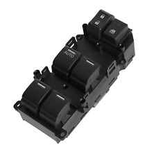
Master Power Window Switch Front Left Driver Side for 2008-2012 Honda Accord
$40.00
